Hi. In this article I will tell you about a rendering technique known as raymarching with distance fields, capable of producing highly detailed images in real-time with very simple code.

slisesix by Inigo Quilez
Before reading on, perhaps you would like to try the interactive WebGL demo?
Content
- Introduction
- The raymarching algorithm
- Rendering techniques
- Iteration based coloring
- Bounding volume
- Fog
- Anti-aliasing
- Lighting
- Shadows
- Ambient occlusion
- Reflections
- Distortion and repetition
- Other
- Conclusion
- Code
- References
Introduction
Raymarching is a 3d-rendering technique, praised by programming-enthusiasts for both its simplicity and speed. It has been used extensively in the demoscene, producing low-size executables and amazing visuals. The most frontstanding figure behind its popularity, is Inigo Quilez, promoting it with his presentation at nvscene: Rendering Worlds With Two Triangles.
The idea is this: Say you have some surface in space. You don't have an explicit formula for it, nor a set of triangles describing it. But you can find out how far away it is, from any point. How would you render this surface?
First of all, we need to find out which points that lie on the surface, and what pixels they correspond to. To do this we use a technique known as ray-casting.
Imagine you and your monitor being placed in this virtual world. Your eye will be looking at a rectangle (your monitor), which we shall call the image plane. Ray-casting works by shooting rays from the eye through each pixel on the image plane, and finding the closest object blocking the path of the ray. Once we hit an object, we can compute the color and shading of the corresponding pixel. If the ray does not hit anything, the pixel is colored with some sky color.
There are several ways in which we can calculate the intersection, for example we analytically solve for it. A raymarcher, however, looks for an approximate solution, by marching along the ray in steps until it finds an intersection. By controlling the step size using a distance field, we can reach blazing speeds, even on a regular laptop GPU.
The raymarching algorithm
In traditional raytracing, a scene is often described by a set of triangles or spheres, making up a mesh. Using some spatial acceleration structure, we can quickly solve for the exact intersections between the rays and the objects.
With raymarching however, we allow for some leeway in the intersection, and accept it when a ray is close enough to a surface. This is done by marching along the ray at step sizes, and checking whether or not the surface is within a given threshold. We can set a limit on the number of steps to prevent marching into oblivion. In code the algorithm looks like this:
bool raymarch(vec3 rayOrigin, vec3 rayDirection) {
    float t = 0.0f;
    for(int i = 0; i < maxSteps; ++i) {
        float d = sceneDistance(rayOrigin + rayDirection * t);
        if(d < epsilon) {
            // Do something with p
            return true;
        }
        t += d;
    }
    return false;
}
But this can be slow if the step size is small, and inaccurate if the step size is large. So we speed things up by implementing a variable step size, and that is where distance fields comes in.
The basic idea is to make sure every surface in our scene is given by a distance estimator (DE), which returns the distance to it from a point p. This way, we can find the distance to the closest surface in the scene, and know that we can step this far without overshooting.

In the figure above the distance field is evaluated at various points along the ray. At the first point (the eye) there is quite a large distance to the closest surface, so we step that far to the next point. This continues until we get close enough to say we hit the surface.
Distance estimators
Consider a sphere centered at the origin with radius r. The distance from a point p to the sphere is given by:
float distSphere(vec3 p, float radius) {
    return length(p) - radius;
}
This function gives us signed distance, because the distance is negative or positive depending on whether we are inside or outside the sphere. In the later sections we will see that this is important in order to compute the surface normal.
Coming up with your own DE's can be difficult, so feel free to take a look at this page, by Inigo Quilez, for a list of distance functions. A useful trick though is to take advantage of symmetry. For example, a box at the origin can be split into the 8 octants, but we do not need to handle each region on its own. Instead we can take the absolute value of the point, and then compute the distance.
The distance field
Once we have the distance to each surface, the scene can be described by a function returning the minimum of them, i.e.:
float distanceField(vec3 p) {
    float d1 = sphere_of_radius_one(p)
    float d2 = box_one_unit_to_left(p)
    return min(d1, d2);
}
We expect that this function provides us a lower-bound on the closest object. It is therefore important that the distance estimators do not under-estimate the distance, as we might risk overshooting.
Various operations can be performed on the distance fields. For example, the union of two distance fields is the minimum, the intersection is maximum, and the complement is the negated distance (assuming it is signed). This is described in more detail at the above mentioned page.
A simple scene
It's time to put the theory to the test. But how do we go from pixels in the image, to points in our virtual world?

Let's say that our window has a position and orientation in the world, the image plane. For the sake of simplicity, we scale it down to a rectangle of width and height 2 units. We define a pair of coordinates, u and v, both going from -1 to 1, representing the corners of the rectangle. This way, the top-left corner of the window (0, 0), becomes (-1, 1) in uv-coordinates. While the bottom-right corner becomes (1, -1).
We decide the orientation of the rectangle by defining an up-vector and a right-vector. A point on the image plane in world-coordinate is then:

For this scene, let's say that we fire rays perpendicular out of the image plane. If our up-vector is along the y-axis, the right-vector is along the x-axis, the forward-vector is either down the positive or negative z-axis. The former can be found by crossing the right vector with the up vector.
Our scene is now everything from -1 to 1 on the x- and y-axis, looking down the positive z-axis. We position the eye at [0, 0, -1], and have a single distance function: a sphere of radius 0.5. If the raymarch function hits the sphere, we color the pixel white, else we color it black. The code for this fits nicely in a shader:
void main()
{
    vec3 eye = vec3(0, 0, -1);
    vec3 up = vec3(0, 1, 0);
    vec3 right = vec3(1, 0, 0);

    float u = gl_FragCoord.x * 2.0 / g_resolution.x - 1.0;
    float v = gl_FragCoord.y * 2.0 / g_resolution.y - 1.0;
    vec3 ro = right * u + up * v;
    vec3 rd = normalize(cross(right, up));

    vec4 color = vec4(0.0); // Sky color

    float t = 0.0;
    const int maxSteps = 32;
    for(int i = 0; i < maxSteps; ++i)
    {
        vec3 p = ro + rd * t;
        float d = length(p) - 0.5; // Distance to sphere of radius 0.5
        if(d < g_rmEpsilon)
        {
            color = vec4(1.0); // Sphere color
            break;
        }

        t += d;
    }

    return color;
}
I believe it's much more exciting if you do this yourself, so I'll let you render this on your own ;)
Perspective
Notice that in the first example, the ray direction was equal to the forward vector, causing every ray to be cast perpendicular to the image plane. This is actually how orthographic projection works, and is not very three-dee-y. What we want, is an illusion of depth. To do this, we can simulate a pinhole camera by positioning the eye behind the image plane, like so:

The distance between the eye and the image plane is analogue to the focal length of a camera lens and focal point. The best part is, this does not change the behaviour of the rays, but merely what direction we cast them!
A point on the image plane is now given by:

where f is the distance between the eye and the image plane, along the forward vector.
The ray direction can now be found by taking the difference between the image plane position and the eye.
Rendering techniques
A simple black or white image is not too exciting. Alot of these can be found both in the presentation mentioned in the introduction, and various pages in this thread.
Iteration count
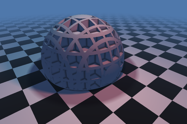
A quick way to spice things up, is to let the color depend on the ray step count. That is, how many steps the raymarch function performed before bailing out or hitting a surface. This will allow you to see where the most intensive portions of your image are.

Iteration-based coloring. The maximum step count was set to 64.
Bounding volume
We can speed up the raymarching if we limit the rays to a certain bounding volume.
Remember that in the raymarching function we repeatedly calculate the distance to the closest surface, and travel along the ray direction by this amount. The sum of the distances will be how far the ray has traveled so far. Using this, we can drop a ray as soon as it is further away than some limit.
Fog
Fog is important to get a sense of scale and distance, and can be used to avoid artifacts in the distance.
To get fog, we can simply blend the distance from the eye with the sky color. In the simplest case, we can define the near- and far-clipping planes to have blending factors of 0 and 1, respectively, and linearly interpolate between these based on the distance.
More realistic blending methods can be found here.
Anti-aliasing
Instead of casting a single ray per pixel, we can distribute multiple rays inside a single pixel, sum the results and calculate the average. This will effectively remove sharp edges, and wreck your framerate at the same time, so be careful.

An interesting optimization could be to only perform AA if the iteration count is above average, as it likely indicates the edge of an object.
Lighting
A simple lighting model is the Lambertian reflectance model. The idea is that the light intensity at a point depends on the angle between the surface normal and the direction to the light. By clamping the dot product of these vectors between 0 and 1, we get a measure for how strongly the point should be lit. For more on lighting models, Arcsynthesis' tutorial explains the topic quite well: Arcsynthesis: Lights on.
We need to compute the surface normal. Our distance function is special type of function known as a scalar field, because it assigns each point (x, y, z) a scalar quantity (the distance to the closest surface). Knowing this, we can approximate the surface normal using what is known as the gradient.
The gradient of a scalar field is a vector, pointing in the direction where the field increases or decreases the most. Its magnitude is how big this change is. Naturally, the distance to a surface will increase more if we move normally away from it, rather than parallell to it. Thus, the gradient points in the same direction as the normal.
The gradient can be approximated by numerical differentation, and normalized to give us the surface normal. The lighting of the point can now be computed. For example:
vec4 shade(vec3 p)
{
    vec3 normal = getNormal(p);
    vec3 lightDir = normalize(lightPosition - p);
    float LightIntensity = lightColor * dot(normal, lightDir);
    return getReflectance(p) * lightIntensity;
}
Shadows
Light rarely looks good without shadows. Luckily for us, this is fairly easy to implement. Simply check if the path from the point to shade to each light source is obstructed or not, by raymarching. This will produce a hard-shadow, but it is possible to get good looking soft-shadows, almost for free.

Ambient occlusion
Once we have obtained the surface normal (see the section about Lighting), we can easily fake an ambient occlusion effect. A proposed method is to sample along the surface normal a couple of times, comparing the value of the distance field with the actual distance from the surface. For example, if the difference is 0, the surface is not occluded. If there are other surfaces closer to the ray at the sample point, the difference will be non-zero.

Reflections
A simple reflection can be calculated by raymarching off the surface normal, and blending the result together with the surface color.
Domain distortion and repetition
Objects can be distorted by manipulating the point checked against in the distance functions. For example:
float twistedCube(vec3 p) {
    vec3 q = rotateY(p, 0.5 * p.y);
    return cube(q);
}
This will produce a cube rotated more or less along the y-axis:

A scene can be repeated by taking the modulo of the point by some size:
float repeatedCubes(vec3 p) {
    p.x = mod(p.x, 1) - 0.5;
    p.z = mod(p.z, 1) - 0.5;
    return cube(p);
}
Which results in many cubes repeated in the xz-plane:

By combining domain repetition with subtracting distance fields from eachother (as described in the beginning), we can make complex objects like this:
 Domain repeated cubes are subtracted from a non-repeated, larger sphere
Be careful though, as distorting the distance field like this can cause some nasty artifacts. A sort-of solution is to step shorter in the raymarching function than the distance field returns.
Other
While distance fields has been a major focus of this article, raymarching itself is a general method. The main advantage is that the algorithm makes it very easy to render a variety of scenes with high level of detail. For example terrain:
Consider a heightmap describing your terrain. It could be a texture sampler uploaded to your shader, or it could be created procedurally. In order to render the terrain by raymarching, you would simply cast rays through each pixel of the image, step along the ray by some size, and stop whenever the point on the ray is lower than the terrain. The color can then be determined by perhaps making taller points white (i.e. snow) and lower points green (i.e. grass). We can shade the point by raymarching towards a lightsource.
See Terrain marching for a nice introduction.

Ixaleno/rgba by Inigo Quilez
Conclusion
In summary, raymarching is a general technique that can be used to render a variety of complex scenes. It fits perfectly in the GPU, as each pixel can be calculated independently. By using distance fields, we can accelerate the rendering to real-time speeds, and still maintain a high level of detail. A number of techniques have been developed for manipulating the distance fields, such as blending, distorting and repeating objects. Furthermore, it is easy to implement graphical improvements, such as ambient occlusion, lighting, soft shadows and bump mapping.
If you think this is really cool, feel free to indulge in the links below. For a more thorough walkthrough of the raymarching algorithm, see Hvidtfeldt's article series, where he also investigates 3D fractals!
I recommend looking through the pouet threads, which are packed full of colorful inspirations and helpful code.
Happy coding!
References
- Inigo Quilez: Raymarching Distance Fields
- hvidtfeldts: Distance Estimated 3D Fractals
- Inigo Quilez: Modeling with Distance Functions
- Inigo Quilez: Free Penumbra Shadows for Raymarching Distance Fields
- John C. Hart: Sphere Tracing: A Geometric Method for the Antialiased Ray Tracing of Implicit Surfaces (1994)
- fractalforums: Kaleidoscopic (escape time) IFS/)
- pouet: Raymarching beginner's thread
- pouet: Raymarching toolbox
Code
An interactive WebGL demo can be found here.
A Github repo for the project can be found here. The repo contains C++ code, which runs with GLFW and OpenGL ver. 3.2. It also contains the source for the WebGL implementation inside the "webgl" subfolder.
Thanks
Special thanks to Inigo Quilez (iq) for his efforts in the demoscene on this topic, as well as various forum members of pouet.net, for being super helpful. Hvidtfeldt's introductory articles were well-written and very useful for gaining an understanding of the topic.
Excellent article! Probably one of the clearest explainations I have encountered! I am starting a project with similar attributes as the one on your github also using c++ and GLFW, I downloaded your source code to try and better understand it myself though I can't seem to get the shaders to work, though other shaders do work.
ReplyDeleteAny Ideas?
Or do you have an email where I could possibly ask you a few questions?
DeleteIt's hard to say what's not working without more info.
DeleteIf the shaders don't compile they'll print an error to cerr - you could look at that output to see what's wrong.
You'll probably want to support OpenGL 3.1 or better to run it though, but you can try changing the #version to something lower, like #version 130.
Excellent, excellent introduction to the subject, both in terms of content and divulgative style. Such a fine work.. Congrats!
ReplyDeleteFantastic article! Helped with a lot of understanding. I have set up a ray marcher following your guidelines, but rendering a cone or cylinder (found on IQ's site) causes it to render infinitely in one direction (cone) and both directions (cylinder). I found another cone function on Pouet.Net that works nicely too however, the normals do not work causing a large black spot on the object.
ReplyDeleteAny ideas on how I could fix this? Its been vexing me for days
Best article I found, you made it easy to understand, thanks! :)
ReplyDeleteThis is the best article I've found on this subject. Would it be possible to expand on how to do anti-aliasing with a worked example in GLSL (or could somebody provide a link to one), I am trying to get my head around it and the Hart paper is too technical...
ReplyDeleteVery cool! I'll be redirecting newbies here when I they ask me about distance fields from now on/
ReplyDeleteI'd add a www.shadertoy.com link in the references, since it's kind of the defacto place to find Raymarched Distance Fields (https://www.shadertoy.com/browse in particular for a quick look of the technique can do)
This post is the greatest greatest reference for raymarching distance fields ever! Thanks!
ReplyDeleteThis is great. It's nice to have this concise explanation to look at along with Inigo's robust content on his blog. Thanks for writing this.
ReplyDeleteCan someone get i.q. to fix all the errors on his distance fields functions please?
ReplyDeleteI've documented them in my Ray Marching tutorial here:
https://www.shadertoy.com/view/XllGW4
I have two questions... I can't find any good books on Raymarching. Uint9 is it possible to use your shaders in my game engine? I can convert your code to Mac OS X BTW ;-). Also Michael Is it possible to use your PoHo lesson too? BTW your twist code could be simplified with Uint9's code. My website is at www.solarfusionsoftware.com . You can post here or email me at my website. Thanks.
ReplyDeleteI have a question, How can we construct "distance estimate function" (signed distance function- SFD) with complex geometry, i only find some examples with symmetric geometry (Cube,Sphere...).I follow below article :http://jamie-wong.com/2016/07/15/ray-marching-signed-distance-functions/#the-raymarching-algorithm. Anyone can show me how to apply this algorithm to rendering a Game,etc ...
ReplyDeleteHello. Just wanted to say that this article got me into shader programming 4 years ago. I have put 522 shaders on shadertoy (252 public, the others are very experimental) and i have a bunch on github as well. It rekindled my interest in programming again as I started once many years ago to do cool graphics. So thanks alot for writing this article, it is a very important article to me.
ReplyDelete